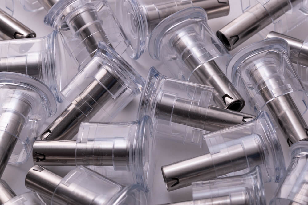
Prototype Overmolding and Insert Molding
Overmolding and insert molding provide a design engineer with some unique capabilities. Overmolding refers to a single part that has a rigid plastic substrate with a softer elastomer overmold. The elastomer can be either mechanically captured by the substrate or by selecting a material combination that will bond at the interface between substrate and overmold.
It’s common to use overmolding to design parts that are used for sealing. The rigid portion allows assembly and support, while the softer elastomeric portion provides a seal. Grip features are standard. The toothbrush is a toothbrush where the softer elastomer provides grip. Overmolding allows the engineer to apply color since both the substrate and the overmold can be different colors.
Insert molding involves placing a part that is typically metal but can be other materials such as ceramic inside the mold and then molding plastic around the metal to yield a single part. A common application of insert molding is the addition to threaded inserts to the housing and assembled using machine screws.
Request More Information
What is Overmolding?
Overmolding is a two-step molding process that is also sometimes called two-shot molding. Step 1 involves molding the rigid plastic substrate. Step 2 involves overmolding a softer elastomer material onto the rigid plastic substrate from step 1 to form a single part. In high-volume production, this typically involves a rotating, multi-cavity mold. While one side of the mold is molding the substrates, the other side of the mold is overmolding the substrates from the last substrate cycle. When this cycle ends, the overmolded parts are ejected, the substrates are rotated into position for overmolding, and a new set of substrates is molded, and so on.
Prototype overmolding achieves the same result by fabricating two separate molds. The first prototype mold is used for injection molding the rigid substrate part. The second prototype mold is used for overmolding the softer elastomer over the rigid substrate.
After setting up the first prototype mold in the molding machine, a quantity of substrates is molded and allowed to cool and shrink. Then the second prototype mold is set up in the molding machine. Rigid substrates are manually placed into the second prototype mold, and soft material is overmolded onto the rigid substrate.
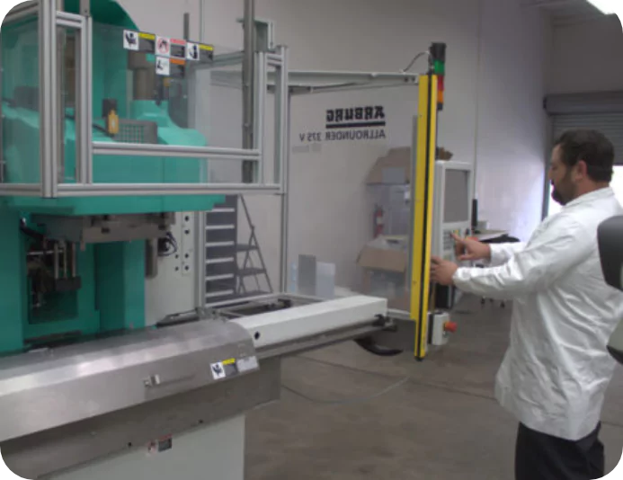
A unique form of overmolding is a specialized molding machine with two injection barrels. This allows two different plastics to be injected into the mold, allowing for molding a single part containing layers of each plastic. Few applications require co-injection molding. An improved food container requires one plastic for assembly to a lid and a second plastic that functions as an oxygen barrier.
Overmolded Prototype Examples
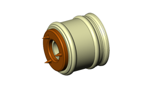
Overmolding Example Part
Overmolding example – Polycarbonate substrate is shown in orange, and flexible TPE overmold is shown in yellow
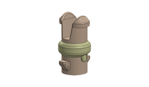
Overmolding Example Part
Overmolding example – A complex micro molded COC substrate is shown in orange and a flexible TPE overmold is shown in yellow.
Overmolding and Insert Molding Design Considerations
The substrate and overmold need to both obey general injection molding rules. Wall thicknesses must be consistent; the draft must be included to allow for part ejection, ribs must be approximately 6% of the base wall thickness, etc. However, a few additional molding rules apply to the design of overmolded parts.
When designing an overmolded part, there should be a shutoff for the overmold. In the example shown, the substrate is shown in yellow, and the overmold is shown in orange. The blue highlighted surface is the shutoff surface. When the substrate is placed in the mold for overmolding the elastomer, the steel in the mold contacts this shutoff surface, which creates a positive seal that prevents the overmolded elastomer from flowing outside the constrained area. An example of poor shutoff design is also shown. There is no shutoff surface available. There will need to be a small amount of clearance between the outer diameter of the substrate and the mold cavity. The elastomer overmold has the potential to flow into this gap because there is no shutoff to prevent overflow from occurring.
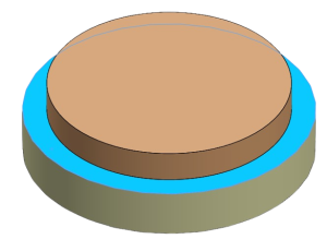
Example of proper shutoff design
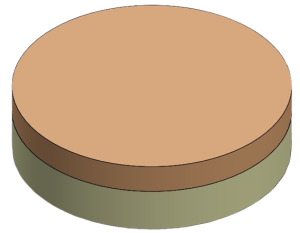
Example of poor shutoff design
In addition to shutoff surface design considerations, insert molding requires capture features that allow the metal insert to be properly placed and held in the mold during overmolding. In this example, the blade has an internal slot feature that can be used to capture the blade in the mold. The second image shows the blade placed in the mold with the two blue highlighted features protruding through the blade to provide capture of the blade. As shown in the last image, the final part will have slots through the plastic and blade in order to provide capture features for insert molding.
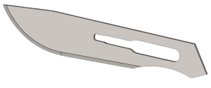
Example of the blade to be overmolded
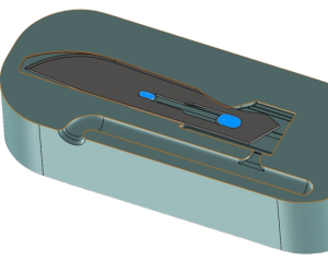
Example of blade capture features in mold, highlighted in blue.
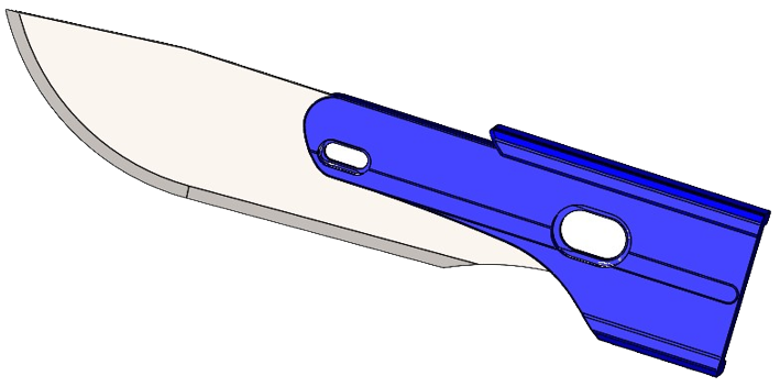
Plastic handle to be molded around the blade.
Prototype Overmolding Material Selection
Overmolding involves first molding a substrate material that is overmolded by one or more materials to form a single part. The most common application is a toothbrush. A rigid substrate is overmolded by a flexible elastomer that functions as a grip feature. Material selection is critical since it requires selecting a compatible material pair. Part design is also important to ensure that the overmold is properly captured and/or bonded to the substrate as well as ensuring all shutoffs prevent flashing of the overmold.
For example, when searching for an elastomer that will bond to polycarbonate with a durometer of 40-50 shore A, one of the candidates presented is Avient Versaflex OM 1245X-1. A review of the specification sheet for this material indicates that it will bond to polycarbonate and has a durometer of 46 shores A, so this grade of elastomer would be a good fit for the application.
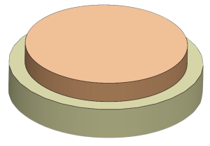
Example of bonded overmold.
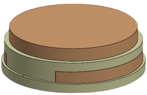

Example of mechanically captured overmold
As an alternative to bonded overmold materials, the elastomer may be mechanically captured by the substrate. This may occur when the application requires selecting a substrate and elastomer combination that does not have a suitable bonding grade available. The image to the right provides an example of a mechanically captured overmold. The rigid substrate is shown in yellow, and the overmold is orange. The slots and holes in the substrate mechanically capture the overmold in a manner that does not require selecting a pair of materials that will bond.
Part Information & Lead Time

Lead Time
Typically, in 1 week, we will indicate the lead time when we provide your quote.

Maximum Molded Part Size
Part may be up to 8″ x 6″ x4″ (200 x 150 x 100 mm)

Maximum Part Volume
Shot volume up to 6 oz (170 g)

Tolerance
Typically <0.004″ (0.1 mm).
Tolerance of 0.001″ (0.025 mm) is possible with certain materials and part geometry. Let’s discuss your application.
What is Insert Molding?
Insert molding is an injection molded process utilized when the design engineer needs to design a plastic part that has one or more integrated metal components. The insert molded component is typically metal but can be other materials such as ceramics. The key criteria is that the inserted material must be able to withstand the heat and high pressure of the plastic during molding. One typical example of insert molding is the use of threaded inserts. Threads can be molded directly into the plastic, and for many applications, this has sufficient strength. However, in applications where the strength of molded threads is not sufficient, then metal threaded inserts may be insert molded into the plastic part to provide much stronger threads.
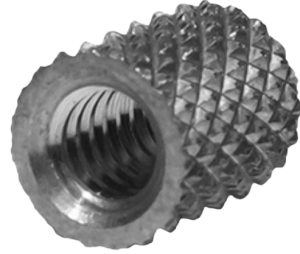
Example of threaded insert
Fabricating molds for insert molding creates a unique challenge because the metal insert is held firmly in place by the mold until the part is ejected from the mold. Part shrinkage starts immediately upon completion of plastic injection while the part is still within the closed mold. This means that the metal insert will act to partially restrict the shrinkage of the plastic when the mold is closed. After ejection, normal part shrinkage resumes, but most of the part shrinkage has already occurred. Therefore, if there is a tight tolerance for the location of the metal insert within the part, it takes experienced molders to assist the design engineer to ensure that the final position of the metal insert meets requirements.
Prototype Insert Molding Examples
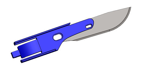
Blade Insert Molding Product Example
A blade shown in gray is that is insert molded with a blue polycarbonate slide.
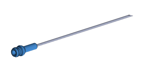
Needle Insert Molding Product Example
A needle is insert molded with a blue polypropylene hub
Part Information & Lead Time

Lead Time
Typically 1 week, we will indicate the lead time when we provide your quote.

Maximum Part Size
Part may be up to 8″ x 6″ x4″ (200 x 150 x 100 mm)

Maximum Part Volume
Shot volume up to 6 oz (170 g)

Tolerance
Typically <0.004″ (0.1 mm).
Tolerance of 0.001″ (0.025 mm) is possible with certain materials and part geometry. Let’s discuss your application.
Overmolding and Insert Molding with Protoshop
Overmolding allows design engineers to achieve multiple functional requirements within a single part that would be impossible to meet without both a rigid substrate and an overmolded elastomer. Manufacturing challenges include the importance of material selection to ensure proper bonding of the elastomer overmold to the substrate and including proper shutoffs in the substrate to constrain the elastomer during overmolding. Insert molding provides design engineers with the ability to integrate metal parts with plastic. Capturing the metal insert in the mold and adjusting for partially constrained part shrinkage requires experienced mold fabricators.
Protoshop has successfully built prototype molds for hundreds of challenging overmolded and insert molded parts. Allow us to lend our extensive industry expertise to review your part design. We will identify any opportunities for improvement so your overmolded and insert molded parts meet functional requirements the first time. At Protoshop, we offer much more than an automated review of your part model. After a detailed review by one of our experienced engineers, we will meet with you online to review a report of our observations, explain why the observations should be adjusted, and answer any questions you may have. Our personal approach to assisting our customers is unique among prototype molding service providers. It is a critical service we offer as it better ensures the success of every prototype mold we build.

