
Plastic Part Design Guide
Introduction to Plastic Part Design
The principals of Protoshop have extensive prior experience in the medical product development industry designing thousands of plastic parts using a wide variety of materials. We find many of the other design guides found online to be lacking in critical information, so we have created our own design guide to help design engineers in their approach to plastic part design.
Plastic part design has an element of art and experience that’s not found in most engineering disciplines. It’s also complicated by rules that can change significantly based on the selected material. For example, part design will typically need to change significantly whether the material to be used is polypropylene vs polycarbonate. However, there are certain rules and considerations that apply across the board for all plastic part designs.
Essential Rules for Effective Plastic Part Design: Molding, Materials, Production, and More
If you follow these simple rules they will cover approximately 90% of plastic part designs. The remaining 10% apply to complex part designs that require the input of someone with extensive knowledge of part design, mold design, and materials. When such complex part models occur, Protoshop is ready to help review your design for prototype molding. The following are your most important considerations for plastic part design:
Request More Information
1
Specifying Material and Wall Thickness for Your Selected Plastic Injection Molding Project
Importance of Material Specifications
It’s important to note that we’ve specified “within the range of the selected plastic.” Each material has a recommended usage range which is between the maximum and minimum wall thickness recommended by the manufacturer. For example, the recommended range of polycarbonate wall thickness is 0.040 – 0.150 inches. We find that most design guides fail to mention the importance of specifying a material PRIOR to starting part design. Too often we find that clients aren’t specifying their materials until its time to begin their prototype molds. That’s relatively late in the development process because the part design has already been through substantial prototyping and testing. Waiting to specify the material creates the risk that changes to the part model may have to occur based on the selected material which would invalidate all previous prototyping and testing. This risk can be avoided by simply specifying the material prior to starting the design. Armed with the selected material and the wall thickness range of that material, the design engineer can then proceed to design the part. There’s the added advantage that finite elements analysis may be performed on the part model when the material is properly specified.
Consistent Wall Thickness for Quality Molding
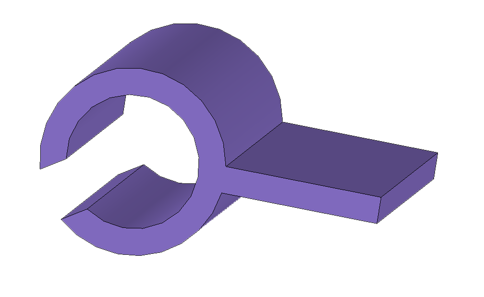
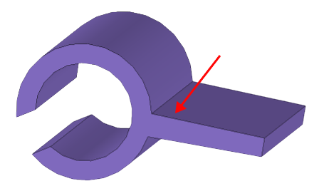
It’s easier to achieve molded parts with consistent lot to lot geometry and tight tolerances when the part is designed with consistent wall thickness. During the molding process, the part cools. During cooling the part can shrink uniformly and consistently without creating distortion if the part is designed with consistent wall thickness. While keeping the wall thickness constant is certainly beneficial, it does not mean that the wall thickness needs to be held constant in order to achieve a high quality molded part. Typically, wall thickness can vary by up to 10% of the wall thickness and still yield high quality parts. For parts designed with greater than 10% wall thickness variation there is an increasing potential for molding defects and increased dimensional tolerances. Some materials are also more tolerant of thickness variation than others. Acrylic (PMMA), for example, is a material that can yield high quality, consistent parts with a higher degree of wall variation. Finally, if your part must have variations in wall thickness, the design engineer should ensure the transition is gradual. An abrupt change in wall thickness is more likely to create molding defects.
Summary on Plastic Wall Thickness:
Select a material before starting the part design
Design the part to have a wall thickness within the material’s recommended wall thickness range
Design the part using constant wall thickness when possible but vary it by no more than 10% with gradual transitions to achieve high quality molded parts
2
Radii
Importance of Radii on External Corners
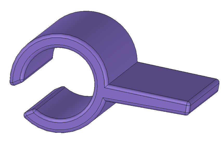
Radii should always be included on external corners of the part. While it is possible to keep the corner sharp, it drives the need to use electrical discharge machining (EDM) instead of CNC machining. While EDM allows for molds to be fabricated with sharp corners, it comes with some significant disadvantages. EDM requires machining multiple electrodes. During EDM, small electrical discharges at the surface of the electrode blast away material when fabricating the mold. EDM is slower, more time consuming, and more expensive compared to CNC machining. EDM also leaves a rough surface that requires polishing. Finally, CNC machining is more accurate than EDM.
Optimizing Radii for Cost and Accuracy
Whenever possible, radii should replace sharp external corners to reduce cost, decrease lead time and to improve part accuracy. In addition, the radii specified should be as large as possible. Small radii require the use of smaller cutting tools during CNC machining. As radii become smaller, the amount of cutting time needed increases significantly which increases mold fabrication cost and lead time. In addition, smaller cutting tools have a greater tendency to bend while cutting which negatively affects accuracy and surface finish. A good rule of thumb is to specify radii that is greater than the feature depth divided by 8. For example, if the feature depth is 0.400” dividing this by 8 is 0.050”. The radii should be at least 0.050”.
Summary on Part Radii:
Radii replacing sharp external corners on parts avoids EDM
Radii should be as large as possible to reduce cost and improve dimensional accuracy
Radii should be greater than the feature depth divided by 8
3
Ribs, gussets, bosses
Guideline for Geometry and Perpendicular Wall Features
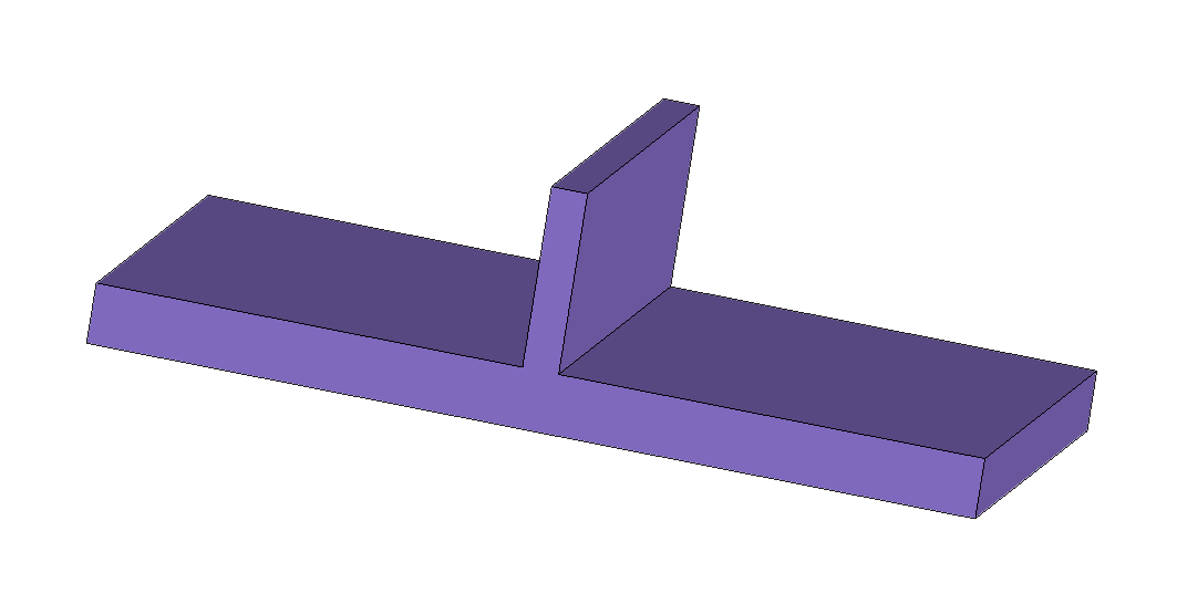
This rule applies to all wall features that are perpendicular to the base wall such as ribs, gussets, bosses, etc. The rule of these features is simple, they should not be more than 60% of the base wall thickness. For example, if the base wall thickness is 0.100”, a perpendicular rib should have thickness less than or equal to 0.060”. A rib that is thicker than 60% of the base wall creates an issue at the intersection with the base wall where the rib is unable to shrink at the same rate as the base wall, creating a molding defect called “sink” that appears as a recessed surface on the base wall. Besides the cosmetic issues of sink, tolerance issues can also occur at the rib as shrinkage is inconsistent.
4
Mold ejection
Importance of Mold Ejection Considerations
Consideration of mold ejection is something that should appear in all plastic part design guides but does not. Too often we see part designs that are otherwise ready for prototype injection molding but have little or no surface area available for ejection.
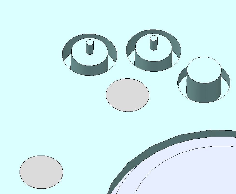
Ejection surfaces are critically important for injection molding. A suitable surface must be designed into the part to allow for ejection from the mold. Ejection unavoidably creates indentations and defects on the part. The surface defects created by ejection are typically variable so care must be taken to ensure proper isolation of functional areas from ejection in the part design.
Designing Effective Ejection Surfaces for Molding
It typically takes extensive part design and injection molding experience to determine whether sufficient ejection surface area has been provided in a part design. We typically tell our clients to allow for circular ejector area of at least 0.105” diameter located a minimum of 0.040” from functional areas at regular intervals across the ejection surface during their first draft of a part design. Most parts require ejector pins between 0.062” and 0250” in diameter. Larger ejector pins are preferred as fewer ejector pins are needed and the quality of ejection is improved. Once a first draft of the part model is created, it is recommended that an expert such as Protoshop be asked to review the part model to ensure that the ejection proposed will be sufficient to ensure proper injection molding.
5
Draft
The use of draft is another term that we find is not adequately described in many design guides. The purpose of draft is to ensure that the molded part may be properly ejected from the mold. The use of draft is important in two different steps of the injection molding process. First, the part needs to be designed with draft in a manner that ensures the molded part stays on the correct half of the mold when the mold opens. Then, draft needs to be sufficient to allow for ejection from the mold.
Another point that is not explained in design guides is that draft does not typically need to be included on the outside wall of a part. This is because shrinkage will pull the outer wall of the molded part away from the mold cavity. The result is a gap such that draft becomes unnecessary. This can be helpful knowledge for part design since draft on both the internal and external side of walls can yield a very thick wall as height increases. By eliminating the external wall draft the wall thickness typically becomes more manageable. Unfortunately, it takes extensive experience with plastic part design, mold design, and materials to specify draft in the proper locations and angle to both ensure the mold opens with the part on the correct side of the mold and ejection from the mold occurs without excessive force or damage to the part. The amount of draft required will highly depend on the part geometry, surface finish, and material used such that no broad design rules for draft are feasible. While most design guides recommend 1-3 degrees, it’s far too complex to provide a simple design guideline. Therefore, our design guide recommends that draft is not something most design engineers will be able to specify without assistance. Design engineers should work with mold design experts such as Protoshop to help specify the draft needed for their part designs. It’s reasonable to start with draft of 1 degree but the design engineer should anticipate that it will need to change and that the design should not be considered frozen until the part design has been reviewed by a molding expert such as Protoshop.
Contact The Experienced Plastic Part Designers at Protoshop
Personalized Support for Successful Molding Projects
We hope that our plastic part design guide is helpful for you. We didn’t want to create yet another generic design guide but wanted to offer a design guide that would offer helpful input for design engineers. Protoshop provides a detailed moldability review followed by a Zoom meeting to review our feedback and to answer any questions our clients may have. We find that this personal attention is critical to ensuring the success of our customers’ injection molding projects.

