

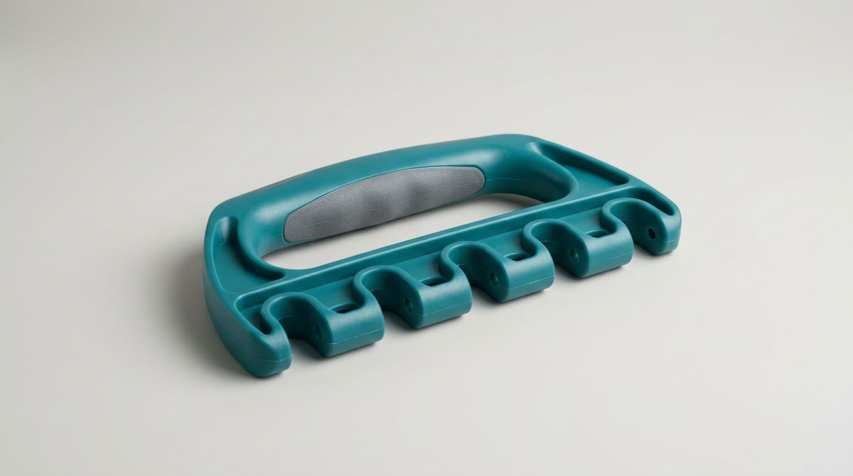
Injection overmolding combines a rigid plastic substrate with a second material, commonly an elastomer, to create an integrated component. In consumer handheld products, it is frequently used for soft-touch housings, grip surfaces, protective zones, and textured interfaces. Rather than assembling these features as separate components, overmolding forms them directly onto the substrate during a secondary injection operation.
An overmolded component’s performance depends on material compatibility, substrate geometry, interface conditions, and differential shrinkage. These variables influence bond strength, dimensional stability, and long-term durability. A component may pass initial dimensional and visual inspection yet develop adhesion or durability failures during environmental testing or extended use.
Evaluating these risks during development allows teams to refine the material combination, part geometry, and molding process before committing to production tooling.
Soft-Touch Overmolding Overview
Overmolding applies a second material to a preformed substrate, typically an engineered thermoplastic. This can be accomplished by placing the previously molded substrate into a separate mold cavity, where the overmold material is injected. This approach provides flexibility during development and allows the substrate and overmold tooling to be manufactured or modified independently.
For high-volume production, more sophisticated two-shot tooling integrates both molding stages into a single system. The substrate is transferred or rotated between injection positions, allowing the second material to be molded onto the first without manually loading the part into a separate mold. However, two-shot molding requires specialized tooling and compatible injection molding equipment, resulting in a substantially higher initial investment. It is generally most attractive when production volumes and cycle-time requirements justify that cost.
The bond between the two materials can result from chemical adhesion, mechanical interlocking, or a combination of both. The bond strength depends on material compatibility, surface conditions, molding parameters, and part geometry.
Thermoplastic elastomers (TPEs) and thermoplastic polyurethanes (TPUs) are commonly used in consumer handheld applications because they offer a range of hardness, flexibility, and impact-absorption characteristics while remaining compatible with injection molding processes. The appropriate Shore A hardness depends on the functional requirements of the product, including grip, compression, flexibility, and tactile performance. Hardness alone, however, does not determine grip quality. Surface texture, friction, geometry, and the stiffness of the underlying substrate also influence the finished product’s feel and performance.
Overmolding can reduce component count by integrating the elastomer and substrate into a single component. Compared with mechanically assembled soft-touch components, this approach can eliminate certain seams and interfaces that might otherwise introduce tolerance variation, joint fatigue, wear, or potential leakage and contamination pathways.
Overmolding does not inherently eliminate these risks. The bonded interface remains an engineering feature that must be designed and validated for the expected loading and environmental conditions.
Material Pairing in Overmolded Products
Injection processing alone does not guarantee adhesion between an elastomer and a rigid substrate. Bond performance is strongly influenced by the chemical compatibility of the two polymer systems, along with interface temperature, surface condition, pressure, and cooling behavior.
Some material combinations develop adhesion through polymer-chain interactions and molecular interpenetration. Others require specially formulated overmold compounds, compatibilizers, or surface treatments to achieve the required bond strength.
Thermoplastic polyurethane overmolded onto polycarbonate is one material combination used in consumer products. Depending on the specific resin grades and formulations, these materials may develop sufficient adhesion without primers or secondary surface treatments. Compatibility should be confirmed with the material supplier and verified through testing under representative molding and service conditions.
Material compatibility must also be evaluated under the intended processing conditions. The degree of interfacial interaction is influenced by temperature and contact conditions, so a material combination that performs adequately within one processing window may respond differently when melt temperature, mold temperature, injection speed, or cooling conditions change.
Material pairing should therefore be treated as a system-level design variable rather than an isolated material-selection decision.
Bond Strength in Plastic Overmolding
Bond strength across an overmold interface is not necessarily uniform throughout the part. Local performance can be affected by material flow, interface temperature, pressure, and the amount of time the two materials remain in contact during packing and cooling.
The end-of-fill region can be particularly important because it may experience different thermal and pressure conditions than areas filled earlier in the cycle. Depending on the material combination and flow pattern, this region may be more susceptible to localized adhesion defects. If it also coincides with a mechanically loaded portion of the component, it can become a potential site for delamination under repeated loading.
Gate location serves a function beyond simply achieving acceptable mold filling. It influences the flow sequence, weld-line locations, pressure distribution, and thermal history across the substrate. Evaluate gate placement in relation to the product’s mechanical loading and expected failure modes, not just filling efficiency. The end-of-fill region is not inherently the weakest area; its performance depends on the combined effects of flow, temperature, packing, and material compatibility.
Packing and hold pressure also affect the interface. Insufficient pressure or inadequate contact during cooling can contribute to localized adhesion defects. These defects may not be visible during visual inspection but can become apparent during mechanical or environmental testing.
Shrinkage and Residual Stress in Overmolding
The elastomer and rigid substrate in an overmolded component may have substantially different shrinkage characteristics. As the overmold cools, it attempts to contract while the underlying substrate constrains that movement.
This differential shrinkage can introduce residual stress into the overmold and across the interface. The magnitude and distribution of this stress depend on material properties, wall thickness, geometry, processing conditions, and how much the substrate constrains the elastomer.
Stress concentrations are especially important near abrupt geometry changes, thin-to-thick transitions, corners, and other areas where the overmold is already under mechanical load.
This behavior can help explain failures in which a component passes initial room-temperature adhesion testing but develops edge lifting or delamination during thermal cycling. Repeated thermal expansion and contraction can increase interfacial stress and contribute to fatigue of the bonded interface.
Overmold validation should therefore consider not only initial bond strength but also the combined effects of mechanical loading, temperature, humidity, and repeated cycling when those conditions are representative of product use.
Mechanical Interlocking in Overmolded Components
Chemical adhesion can provide substantial retention, but mechanical interlocking offers an additional means of preventing separation. This is particularly useful in handheld products where grip surfaces may experience repeated compression, tension, and shear loading.
One common approach is to incorporate through-holes or other retention features into the rigid substrate. During molding, the elastomer flows through or around the feature and solidifies on the opposite side, creating a geometric lock.
Unlike chemical adhesion, mechanical interlocking provides geometric resistance to separation. Its effectiveness depends on the size, placement, and orientation of the retention features relative to the applied loads. Through-holes, undercuts, channels, and wraparound features can help resist pull-off or shear forces, depending on their configuration.
Combining mechanical retention with a compatible material pair can provide additional robustness when the interface is subjected to repeated loading or environmental exposure. However, mechanical interlocking does not eliminate the need for adequate adhesion where the design depends on a continuous bonded interface.
Incorporate these features into the substrate design before tooling. Adding retention features after a mold has been completed can require substantial tool modification and may limit the available design options.
Optimizing Plastic Part Design for Overmolding
Designing a substrate for overmolding requires consideration of both its structural behavior and the requirements of the secondary molding operation.
The substrate must remain dimensionally stable during the second injection operation. The temperature and pressure of the incoming melt can cause localized softening, deformation, or movement if the substrate material and tooling are not appropriately selected. Mold support, locating features, substrate wall thickness, and processing conditions should be designed to maintain the required geometry throughout overmolding. This is particularly important for thin-walled substrates and components with tight dimensional tolerances.
Wall-thickness variation can also cause differential cooling and substrate warpage, potentially preventing the substrate from seating correctly in the overmold tool. Sink marks and surface irregularities on the bonding surface can create local variations in contact geometry and interface conditions.
Draft requires careful evaluation. While draft is necessary for reliable ejection, excessive or poorly positioned draft can reduce the available bonding surface or interfere with the geometry needed to locate the substrate accurately within the mold.
Consistent substrate wall thickness promotes predictable cooling and reduces variation in substrate geometry. The overmold itself also requires attention to thickness transitions. Large changes in elastomer thickness can produce differential shrinkage and localized residual stress. Grip geometry must balance ergonomic requirements with the elastomer’s thermal and mechanical behavior during molding and cooling.
Consider gate location early in the design process because it determines where material enters the cavity and influences the resulting flow pattern, weld-line locations, and pressure distribution. A gate positioned in a highly flexed or mechanically loaded region can create a potential weakness, depending on the material and resulting flow structure. Gate placement should therefore be assessed alongside the component’s intended loading conditions and retention strategy.
Controlling Overmolding Cost
The cost of an overmolded component is influenced by material selection, processing requirements, cycle time, and tooling complexity. Wall-thickness uniformity matters because it affects cooling time and, in turn, cycle time.
Unevenly thick grip sections can require longer cooling cycles and may increase residual stress at transitions between sections. Design features that simplify the tooling can provide additional cost benefits. Conversely, side actions, complex shutoffs, and other mechanisms can increase tooling complexity, machining requirements, maintenance needs, and cycle time.
The choice of molding process also affects total component cost. Separate insert overmolding generally requires a lower initial tooling investment but involves transferring and loading the substrate into the overmold tool. Two-shot molding requires more specialized tooling and equipment but can reduce handling and improve throughput at sufficient production volumes. The most economical approach depends on the balance between tooling investment, cycle time, labor, expected production volume, and the flexibility required during development.
These decisions are easier to address during design-for-manufacturing (DFM) review and tooling design than after the mold has been manufactured. A geometry change that requires only a CAD revision during development can become a physical tool modification once the mold is complete.
Protoshop works with development teams at this stage to identify potential issues before committing to tooling and translate production requirements into a prototype mold designed for meaningful functional validation.
Prototype Validation for Overmolded Parts
Simulation, material data, and analytical methods can provide valuable information during overmold development, but they do not eliminate the need for physical validation. Actual molded parts show how the selected material combination, tooling configuration, processing conditions, and geometry perform together.
Prototype molded parts allow teams to evaluate adhesion, dimensional stability, mechanical retention, surface appearance, and durability under conditions that more closely reflect the intended manufacturing process. Depending on the application, validation may include peel or pull-off testing, shear resistance, dimensional inspection, thermal cycling, repeated compression, abrasion, and exposure to cleaning agents or other relevant chemicals.
Visual inspection alone may not reveal localized adhesion defects or weaknesses that develop under repeated loading. Testing should reflect the product’s intended use and the failure modes most likely to affect performance. For a handheld grip, this may include resistance to edge lifting, repeated gripping forces, and surface wear. For an overmolded seal, testing may focus on leakage, compression behavior, and dimensional stability across the expected temperature range.
The appropriate test method depends on the component geometry and application. Peel, pull-off, and shear tests measure different aspects of interface performance and should not be treated as interchangeable. A representative test plan should evaluate the loading conditions most relevant to the product’s expected service life.
Identifying a failure during prototype development creates an opportunity to modify geometry, material selection, gate location, tooling features, or processing conditions while those changes are still relatively manageable. Discovering the same failure after production tooling has been completed can require tool rework, component redesign, additional validation, and corresponding schedule adjustments.
The objective of Protoshop’s prototype molding process is not simply to produce another set of samples. It is to provide engineering teams with representative parts and actionable manufacturing data before the cost of change increases. From initial DFM review through prototype mold fabrication and molded-part evaluation, Protoshop can help teams identify overmolding risks early, validate design decisions, and enter production with greater confidence in the part and process.
